
NorthSec 2023: The conference badge
During this year’s NorthSec Conference, the participants were given an electronic badge, which allowed interaction between the devices by connecting them in a chain.
This is what we learned about it.
The badge hardware
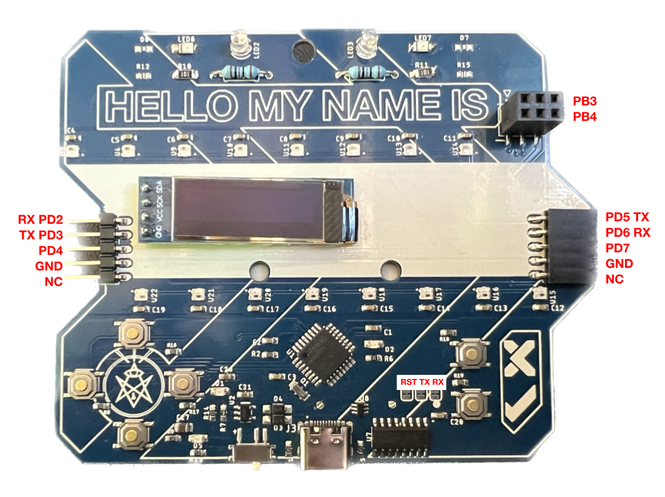
This year’s conference badge was powered by an ATMEL ATMEGA328PB microcontroller, which is a 8-bit microcontroller with 32KB of flash memory and 2KB of SRAM. It is the same microcontroller that is used in the Arduino Uno.
Together with the microcontroller we can find a CH304C USB to serial converter, used for UART communication, a SAO connector, 6 push buttons, an (optional) 128x32 OLED display, 16 WS2812B RGB LEDs.
In the back we can find an AVR ISP connector, used for programming the microcontroller, and a 3xAAA battery holder.
On the sides, we have 2 x 5 pin headers, used for connecting the badges together.
Connections were probed and we were able to determine the pinout of the 5 pin headers on the sides
The game
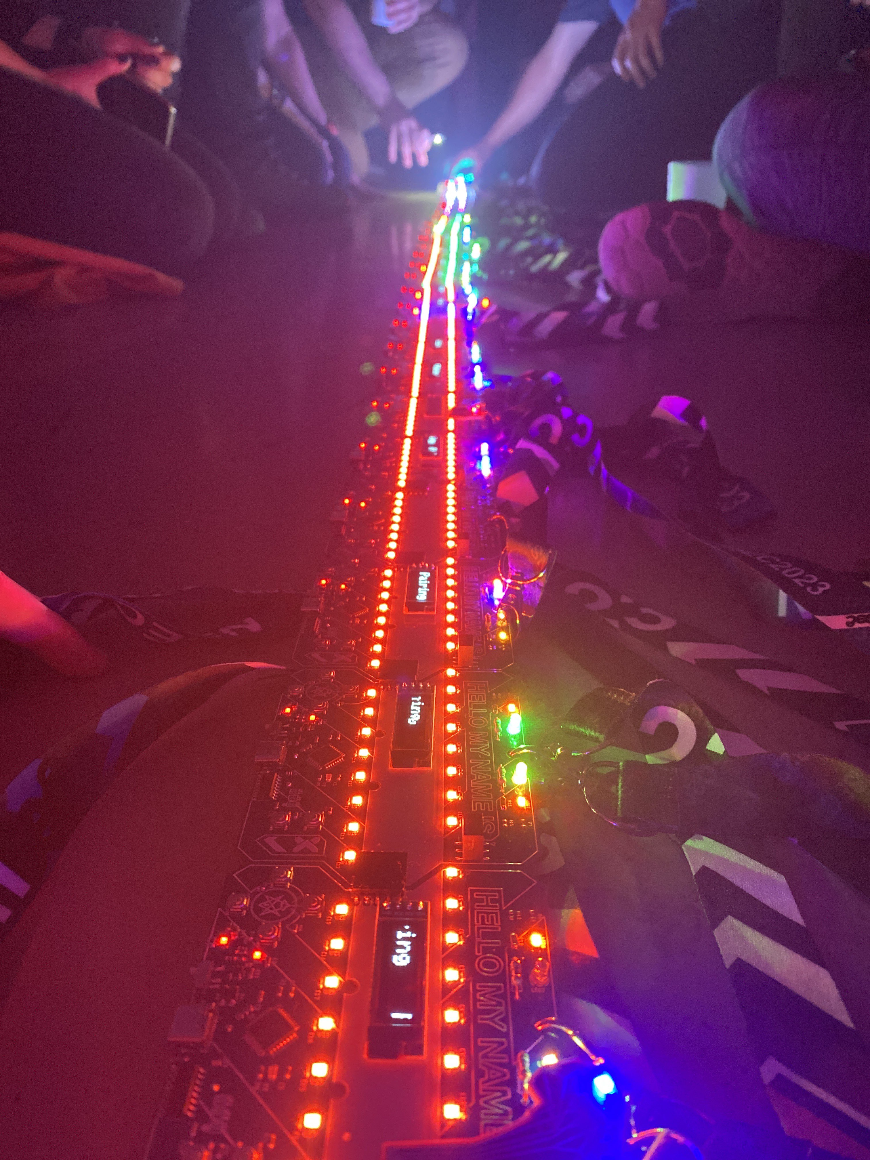
The badge didn’t come with a screen, but by word of mouth people started commenting how the game worked: If you connected your badge to another one, you would get a point. If you connected more than 2 badges together, the points would multiply. The amount of points is determined by the amount of new badges by the amount of badges in the chain not counting yours.
After you earn points, new color patterns would be available for use in the LEDs.
At the soldering village you could install the OLED display which would give you a better idea of what was going on. Once badges are connected to each other, the display would show the word Pairing, and a light sequence would run through all the connected badges.
Once the communication was finished, the OLED would show how many new badges you’d seen, and the amount of points you earned.
Dumping the flash
We had played the game a few times, but we wanted to learn how this was implemented. We dumped the firmware and EEPROM contents using the AVR ISP connector in the back and the avrdude tool, paired with a Flipper Zero and the AVR Flasher app.
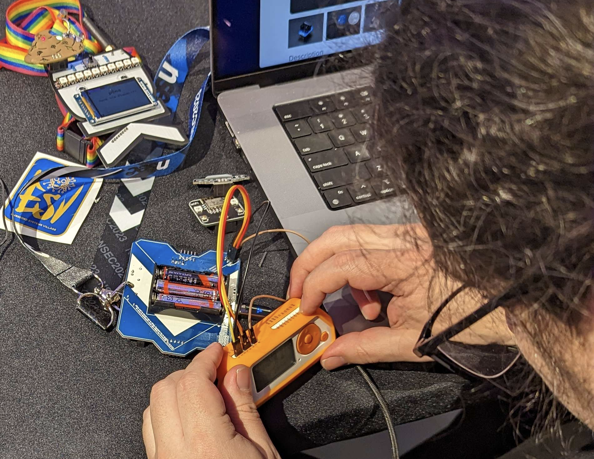
Example: reading the EEPROM contents, Flipper AVR Flasher app must be in ISP Programmer mode:
avrdude -p m328pb -c stk500v1 -P /dev/tty.flipper -U eeprom:r:eeprom.bin:r
By doing some brief visual analysis and comparison of the EEPROM contents, we could see that the points count was stored in the 5th byte, and the currently selected light pattern is stored in the 3rd byte. You can also see your name starting on the 6th byte, and on address 0x0000002C you can see the beginning of the list of badges you’ve seen.
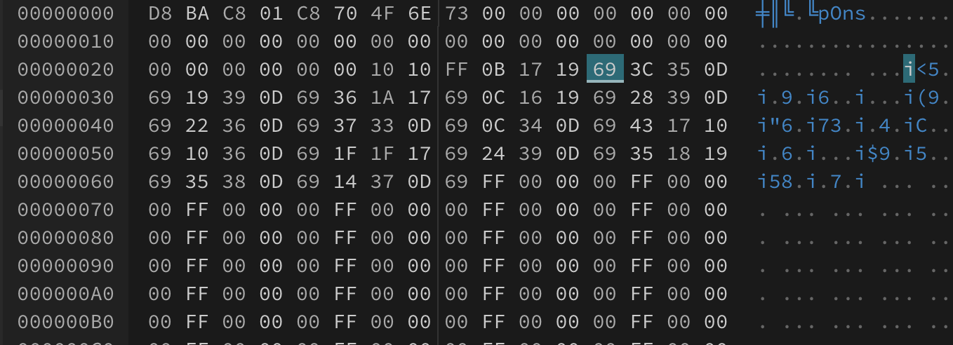
This way we could easily set the value of the 5th byte to FF and get the maximum amount of points, which is 200. After booting, the stored value would change to C8.
The communications protocol
We wanted to understand how the badges were communicating, and to do so, Clayton hooked up his logic analyzer to the connectors on the side of the badge, and determined that the third pin was a sensing pin. When this pin was grounded, we saw activity in the TX pin on the right side connector.
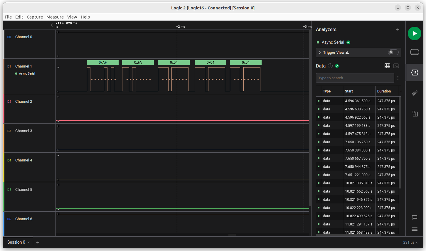
The communication turned out to be Async Serial with Inverted Polarity, 38400 baud, 8N1. This was probably implemented using Software Serial, as the ATMega328PB only has one hardware UART, and it was already connected to the CH304C USB to serial converter.
Next, we proceeded to record the conversation between 2 and 3 badges using the logic analyzer. We noticed all packets started with the sequence 0xAF 0xFA, followed by the type of packet, and a payload.
It was later determined that this payload contained a Fletcher Checksum, which is a simple checksum algorithm used to detect errors in data transmission.
Clayton quickly wrote a python script to analyze the packets, count their ocurrences and their sequence in the conversation. This gave us a better idea on the types of packets we were seeing.
In a 3 badge conversation, excluding 03 and 07:
Setup:
 3.532 1_to_2 affa05050a00
 3.591 1_to_2 affa040404
 5.061 1_to_2 affa05050a00
 5.443 2_to_3 affa05060b01
 6.304 2_to_1 affa040404
 6.797 1_to_2 affa05050a00
 7.234 1_to_2 affa05050a00
 7.675 1_to_2 affa05050a00
 8.033 2_to_3 affa05060b01
 8.384 3_to_2 affa06090f03
 8.719 2_to_1 affa06090f03
 9.153 2_to_1 affa06090f03
 9.584 2_to_1 affa06090f03

Progress:
18.163 1_to_2 affa0b0b0b
27.150 2_to_3 affa0b0b0b
45.818 3_to_2 affa0c0c0c
54.914 2_to_1 affa0c0c0c
63.709 1_to_2 affa0d0d0d
64.024 2_to_3 affa0d0d0d

Completion:
72.679 1_to_2 affa0a58c5005330424e474369191619
73.115 2_to_3 affa0a58c5005330424e474369191619
74.105 2_to_3 affa0a5edb015330424e4743690d340c
74.476 3_to_2 affa0a890f025330424e4743690d3337
74.849 2_to_1 affa0a890f025330424e4743690d3337
75.836 2_to_1 affa0a5edb015330424e4743690d340c
This led us to determine the following packet types at the time:
03 - ping?
04 - something setup-related?
05 - setup stage 1, left to right - badge number (left to right, starting at 0)
06 - setup stage 2, right to left - total badge count
07 - ack
0a - serial number exchange
     badge number (left to right, starting at 0) + magic number "S0BNGC" + badge serial
0b - start lighting top row
0c - start lighting bottom row
0d - done with lights
Then, a python script was implemented that would attempt to communicate with the badge, and we were able to get the badge to start pairing. To do this, he used a Raspberry Pi Pico Debug Probe, and inverted the signal using PN2222A transistors to create an inverter.
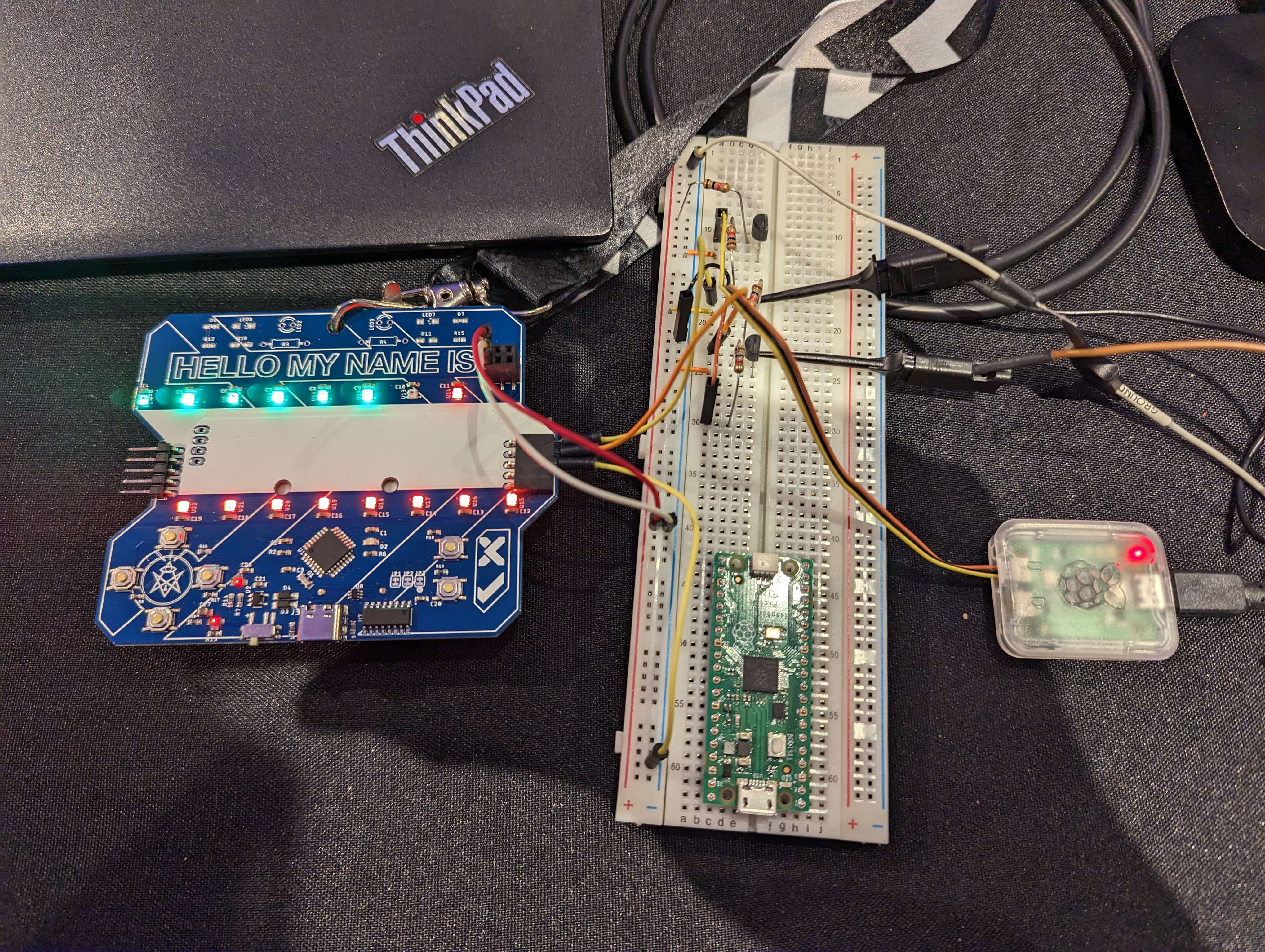
We weren’t able to get past the pairing stage. As the CTF was about to begin we decided to come back to this later.
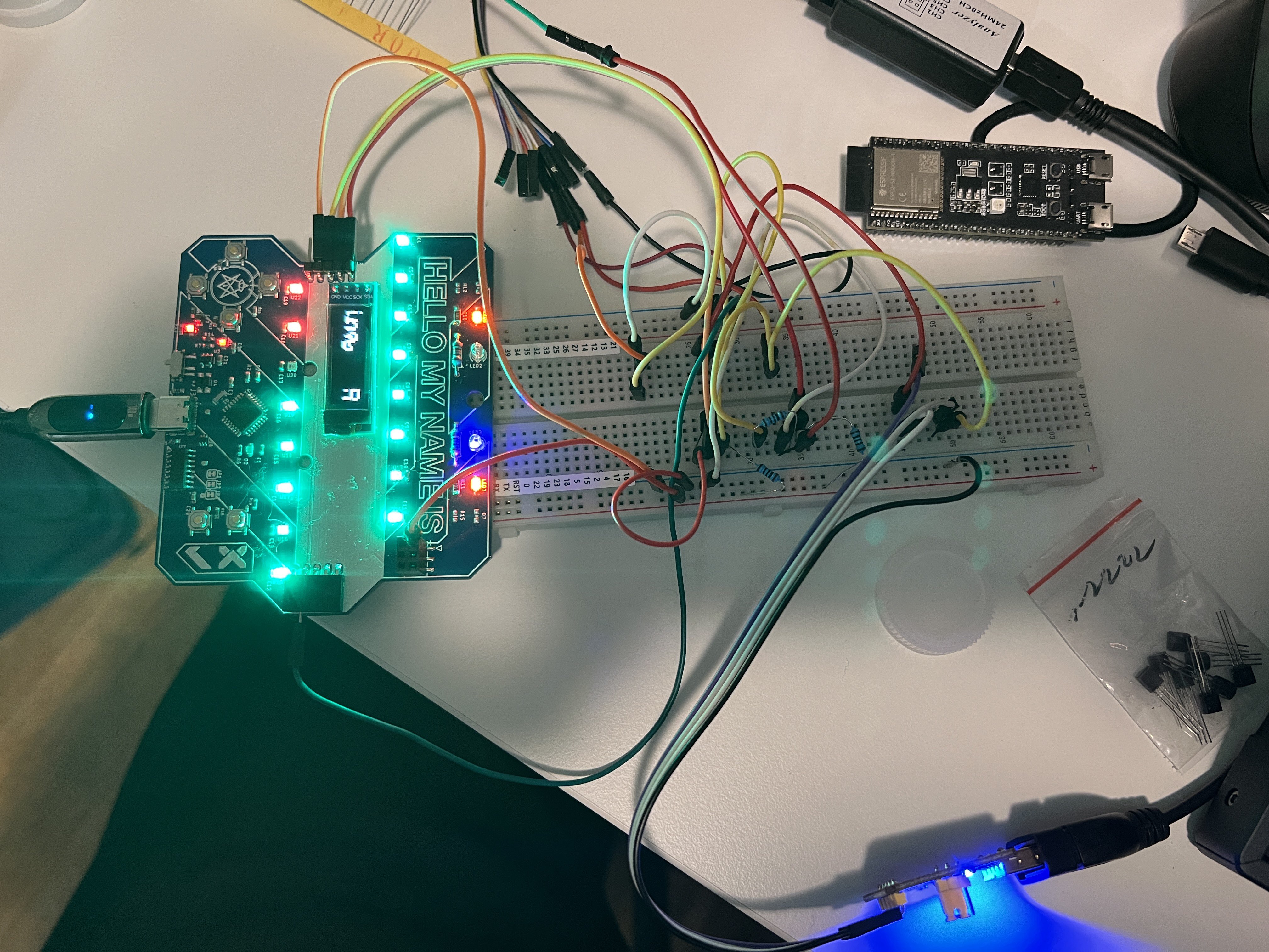
Making the badges talk over the internet
In the meantime, we decided to try to get two badges to communicate over the internet. Clayton and myself connected our badge ports to an inverter and then to a USB to serial converter. Then, we used the socat tool to be able to link the serial ports over TCP.
Server side, on Clayton’s machine. Badge connected to the right side:
socat TCP-LISTEN:31337,fork,reuseaddr,nodelay FILE:/dev/ttyACM0,b38400,raw
Client side, on my machine. Badge connected to the left side:
socat TCP-CONNECT:server:31337,reuseaddr,nodelay FILE:/dev/ttyUSB0,b38400,raw
After a bit, the badges were talking to each other, and were able to successfully pair the badges over the internet.
Finishing the protocol reverse engineering
We wanted to finish understading the protocol, and why we weren’t able to get past the pairing stage. After some careful analysis of the recorded communications, we realized the 0x03 wasn’t a ping message, but some sort of “I’m done” message (which we later learned it’s called a MONITOR message), giving the acknowledging party the opportunity to transmit the next packet.
This allowed us to keep things moving through the pairing process, and were able to simulate the protocol for the badge to believe it’s pairing with another badge.
Pairing to one badge
#!/usr/bin/env python3

import serial
import time

payload_len = {
    5: 1,
    10: 11,
}

def fletcher_checksum(command, payload):
    message = bytes([command]) + payload

    cs1 = 0
    cs2 = 0
    for b in message:
        cs1 = (cs1 + b) & 0xff
        cs2 = (cs2 + cs1) & 0xff
    return cs1, cs2


def read_packet(ser):
    data = ser.read()
    if data != bytes([0xaf]):
        print(f"Expected af, got {data.hex()}")
        return None, None

    data = ser.read()
    if data != bytes([0xfa]):
        print(f"Expected fa, got {data.hex()}")
        return None, None

    data = ser.read(3)
    if len(data) != 3:
        print(f"Expected 3 bytes, got {data.hex()}")
        return None, None

    command = data[0]
    cs1 = data[1]
    cs2 = data[2]

    payload = bytes()
    if command in payload_len:
        expected_bytes = payload_len[command]
        payload = ser.read(expected_bytes)
        if len(payload) != expected_bytes:
            print(f"Expected {expected_bytes} bytes, got {payload.hex()}")
            return None, None

    if (cs1, cs2) != fletcher_checksum(command, payload):
        print("Invalid checksum!")
        return None, None

    print(f"Received: {command} {payload.hex()}")
    return command, payload


def encode_packet(command, payload=b""):
    cs1, cs2 = fletcher_checksum(command, payload)
    message = bytes([0xaf, 0xfa, command, cs1, cs2]) + payload
    return message


def send_ack(ser):
    packet = encode_packet(7)
    ser.write(packet)


def send_packet(ser, command, payload=b""):
    packet = encode_packet(command, payload)

    for _ in range(5):
        print(f"                  Sending: {packet.hex()}")
        ser.write(packet)
        response_command, _ = read_packet(ser)
        if response_command == 7:
            break


def receive_packets(ser):
    packets = []

    while True:
        command, payload = read_packet(ser)

        if command is None:
            continue

        if command == 7:
            continue

        send_ack(ser)

        if command == 3:
            break

        if (command, payload) not in packets:
            packets.append((command, payload))

    return packets


ser = serial.Serial("/dev/ttyACM0", baudrate=38400, timeout=0.5)
while True:
    packets = receive_packets(ser)
    for command, payload in packets:
        if command == 5:
            send_packet(ser, 6, bytes([2]))

        if command == 11:
            send_packet(ser, 12)

        if command == 10:
            send_packet(ser, 10, bytes([1]) + b'S0BNGC' + bytes.fromhex("deadbeef"))

    send_packet(ser, 3)
The final goal: Simulate many badges
After the protocol was reverse engineered, Clayton modified the script to be able to simulate many badges.
Pairing to multiple simulated badges
#!/usr/bin/env python3

import random
import serial
import time

CHAIN_LENGTH = 5
SERIAL_DEVICE = "/dev/ttyACM0"

BAUD_RATE = 38400
SERIAL_TIMEOUT = 0.5
SEND_RETRIES = 5

OP_PASS_TOKEN = 3
OP_UNKNOWN = 4
OP_START_PAIR = 5
OP_CHAIN_LENGTH = 6
OP_ACK = 7
OP_BADGE_SERIAL = 10
OP_GREEN_STAGE_1 = 11
OP_GREEN_STAGE_2 = 12
OP_ALL_GREEN = 13

payload_len = {
    OP_START_PAIR: 1,
    OP_BADGE_SERIAL: 11,
}

PREAMBLE = bytes([0xaf, 0xfa])
BADGE_SERIAL_MAGIC = b"S0BNGC"


def fletcher_checksum(command, payload):
    message = bytes([command]) + payload

    cs1 = 0
    cs2 = 0
    for b in message:
        cs1 = (cs1 + b) & 0xff
        cs2 = (cs2 + cs1) & 0xff
    return cs1, cs2


def read_packet(ser):
    data = ser.read()
    if data != PREAMBLE[0:1]:
        if len(data) == 0:
            print("Timeout")
        else:
            print(f"Expected {PREAMBLE[0:1].hex()}, got {data.hex()}")
        return None, None

    data = ser.read()
    if data != PREAMBLE[1:2]:
        print(f"Expected {PREAMBLE[1:2].hex()}, got {data.hex()}")
        return None, None

    data = ser.read(3)
    if len(data) != 3:
        print(f"Expected 3 bytes, got {data.hex()}")
        return None, None

    command = data[0]
    cs1 = data[1]
    cs2 = data[2]

    payload = bytes()
    if command in payload_len:
        expected_bytes = payload_len[command]
        payload = ser.read(expected_bytes)
        if len(payload) != expected_bytes:
            print(f"Expected {expected_bytes} bytes, got {payload.hex()}")
            return None, None

    if (cs1, cs2) != fletcher_checksum(command, payload):
        print("Invalid checksum!")
        return None, None

    print(f"Received: {command} {payload.hex()}")
    return command, payload


def encode_packet(command, payload=b""):
    cs1, cs2 = fletcher_checksum(command, payload)
    message = PREAMBLE + bytes([command, cs1, cs2]) + payload
    return message


def send_ack(ser):
    packet = encode_packet(OP_ACK)
    print(" "*35, f"Sending: {OP_ACK}")
    ser.write(packet)


def send_packet(ser, command, payload=b""):
    packet = encode_packet(command, payload)

    for _ in range(SEND_RETRIES):
        print(" "*35, f"Sending: {command} {payload.hex()}")
        ser.write(packet)
        response_command, _ = read_packet(ser)
        if response_command == OP_ACK:
            break


def receive_packets(ser):
    packets = []

    while True:
        command, payload = read_packet(ser)

        if command is None:
            continue

        if command == OP_ACK:
            continue

        send_ack(ser)

        if command == OP_PASS_TOKEN:
            break

        if (command, payload) not in packets:
            packets.append((command, payload))

    return packets


ser = serial.Serial(SERIAL_DEVICE, baudrate=BAUD_RATE, timeout=SERIAL_TIMEOUT)
while True:
    packets = receive_packets(ser)
    for command, payload in packets:
        if command == OP_START_PAIR:
            send_packet(ser, OP_CHAIN_LENGTH, bytes([CHAIN_LENGTH]))

        if command == OP_GREEN_STAGE_1:
            send_packet(ser, OP_GREEN_STAGE_2)

        if command == OP_BADGE_SERIAL:
            for badge_num in reversed(range(CHAIN_LENGTH)):
                fake_badge_serial = bytes(random.randrange(256) for _ in range(4))
                send_packet(ser, OP_BADGE_SERIAL,
                            bytes([badge_num]) + BADGE_SERIAL_MAGIC + fake_badge_serial)

    send_packet(ser, OP_PASS_TOKEN)
Conclusion
This was an amazing exercise in reverse engineering and protocol analysis. I learned a lot about serial communication and how to use a logic analyzer, as well as how to make simple inverters using transistors.
We were able to confirm our findings, as the code was released a few hours after we finished our analysis. We also learned the 0x04 packet was a reset packet.
- Conference Badge repo on Github
- Clayton’s write-up about using Raspberry Pi Pico Debug Probe with inverted logic
Thanks to NorthSec and their badge team for this amazing badge. I can’t wait to see what they come up with next year!